Operational Protocol
Authors: Gayathri Satheesh gs2750@nyu.edu, Maitha Al Shaali ma6895@nyu.edu, Haidee Paterson haidee.paterson@nyu.edu, Hadi Zaatiti hadi.zaatiti@nyu.edu
Based on a previous version of the protocol from Aniol Santos Angles.
Find a PDF version of the protocol: MEG Lab manual PDF download
Once you master the current protocol, keep in handy the MEG Session Checklist
Lab booking and schedule
Warning
Bookings should not take place on a Monday morning, as this is when Helium refills are scheduled and it is not possible to acquire data during this period.
Checks Completed by MEG Scientist Prior to Experiment
The MEG lab is provided to the project owner after the following checks and tests have been performed successfully.
- KIT system is in an operational status when:
Helium levels are sufficient to conduct an experiment
Quality of the data from SQUIDs sensor has been verified
Empty-room data has been acquired and noise levels have been computed and assessed
- Vpixx system is operational when:
Trigger events are tested
Projector is in a running state
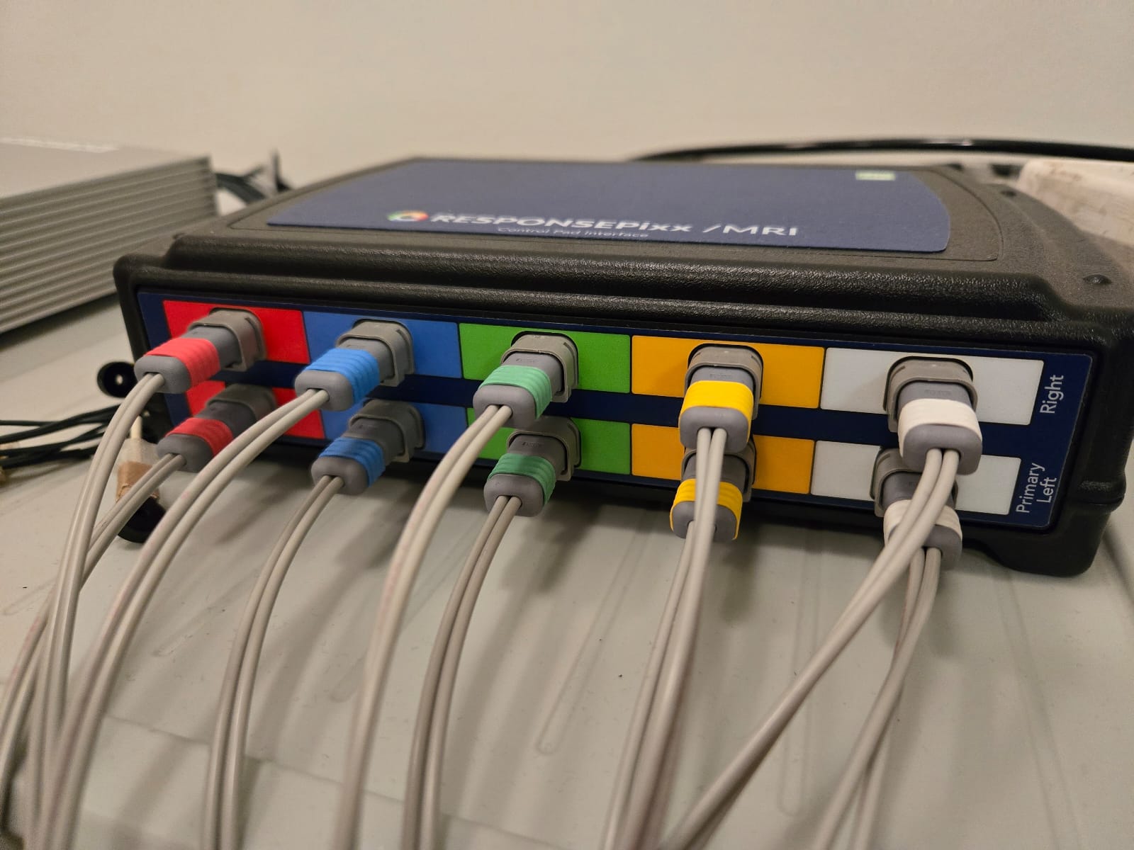
Response boxes must be tested for correct button responses
- Communication system with participant are operational when:
Microphone outside the MSR, to communicate to the participant works correctly
Microphone inside the MSR for participant to communicate with project owner works correctly
Earphones with disposable single use foam earplugs for participant to hear the project owner outside the MSR works correctly
Camera inside MSR for visualising the participant
- Laser scanner system is operational when:
Laser scanner computer works correctly
Laser pointer/surface scanner is operational
- Personal Protective Equipment/Clinical Consumables are available including:
clean foam earplugs
head caps
scrubs
clinical application tape for HPI coils on participant face
gloves
linen
face baby wipes
normal tissue paper
head caps
kitchen towels
glasses for vision correction -6 to +6 in 0.5 increments
a sign to be used if the participant is a female wearing a veil/head covering
Should you require new items please contact the team with your request.
Performed by the project owner - Prepare the lab equipment (prior to participant arrival)
The steps below should be performed by the project owner prior to the arrival of the participant and should be completed in the following the order. These procedures take an estimated time of 20 mins.
- Prepare MSR:
Make sure the MSR has no metal objects inside
Switch the heater off
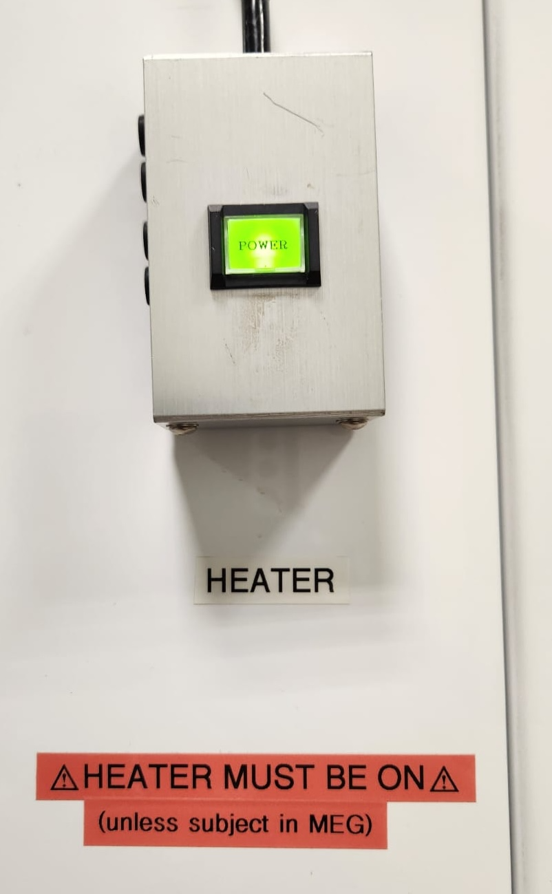
Heater Button
Prepare bedsheets and pillowcases
- Clinical Tape is usually stored in the drawers inside the plastic drawers inside the MSR
or/also in the top right wooden drawer outside the MSR, on the right side of the Stimulus computer
Prepare 12 pieces of tape, those will be used to set the HPI coils on the participant’s head
- Marker box check:
- Ensure that the Marker Box found inside the MSR has enough battery
Power up the Marker Box by flipping the Power switch up
If there is enough battery, the red LED ‘Low batt’ should go on for a second and then back off
- If there is not enough battery, the red LED ‘Low batt’ is either on all the time or never comes on for a second as previously
In this case, change the batteries of the Box, recharged batteries are available under the Stimulus computer
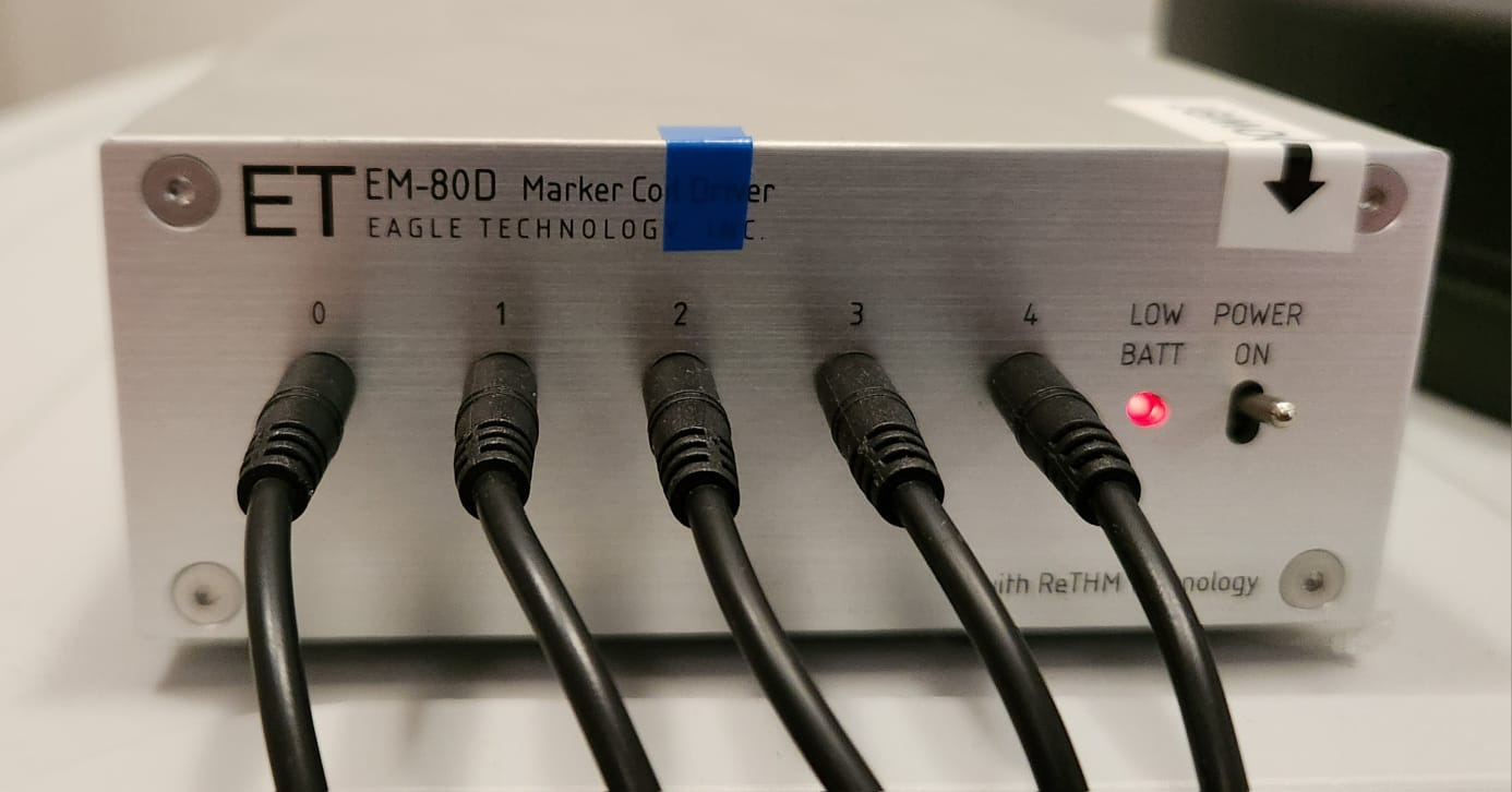
Marker box power indicator
Uncoil the five HPI marker coils that are linked to the Marker Box
- Trigger Box preparation:
The Trigger Box is outside the MSR and pictured below
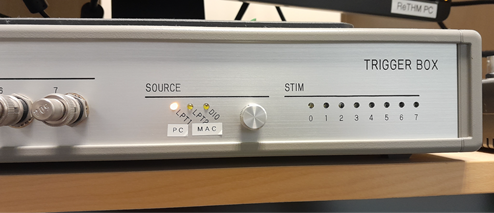
Trigger Box found above the MEG Main PC.
Ensure that the Source button is set to LPT1/PC which is on the left side
- If project owner requires empty-room data prior to experiment:
Turn off the MSR lights and put the light brightness to low
Close the MSR door without a particpant inside
After the previous steps, on the MEG Main PC computer, open MEG160 software
- Then, Menu -> Acquire -> Auto Tuning -> Ok
Wait for the auto-tuning to be done
- From Menu -> Acquire -> MEG Measurement -> Monitor and Acquisition window should open
- In the ‘Sensor Control’ window ensure or set these parameters NB are only to be used for empty-room data and not for a neuro-activity experiment measurement):
HPF to 0.1 Hz
LPF to 1 KHz
BEF to THRU
Click on ‘Sensor Check’
Let the Sensor Check run for around 30 seconds
Uncheck ‘Sensor Check’
Make sure that the sensor display identical sinusoidal wave
Remember that Sensor 91 is broken and will not display a sine wave
In the ‘Data Acquisition’ window enter the following:
Patient ID: sub-emptyroom
Name: sub-emptyroom_<data in YYYYMMDD>
Foldername: C: MEG160Binemptyroom
- After ensuring the MSR door is closed, press Lock
The sensor measurements will oscillate rapidly, wait until the values are stable, i.e., no upward or downward trend is observed
- Continuous Mode -> Start
Set Sampling Rate to 2000 Hz
Set Time to 180 seconds
then, Start Acquisition
When recording is done, press Unlock
Close the MEG Measurement window
Open the MSR door
- Prepare Vpixx systems:
Ensure that the three Vpixx boxes are turned on: Soundpixx, Propixx and Responsepixx
Soundpixx box - all the knobs have to be set as a default to the positions on the image below:
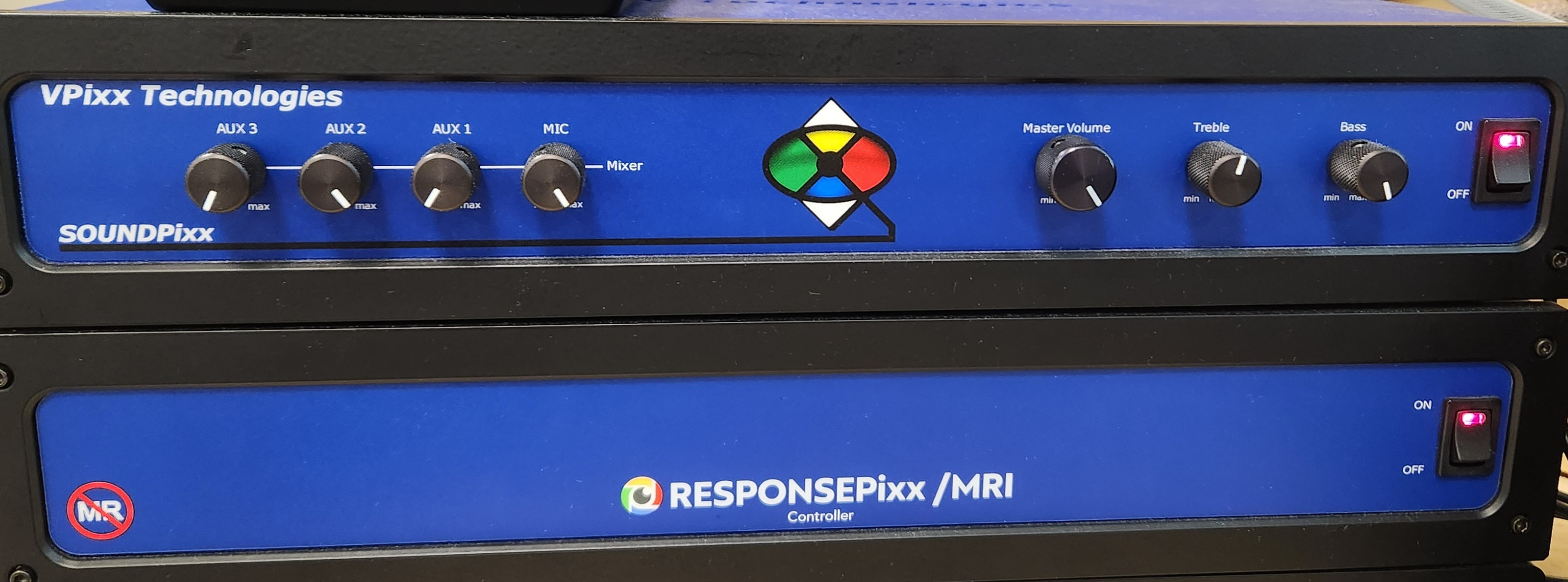
Soundpixx Box knob settings
Turn on the computer if it is off, boot under Windows (it will default to Ubuntu)
- Settings of Vpixx computer. Ensure that:
- Screens are in multiple displays (not mirror display)
Right-click on desktop > Display settings > Extend these displays > Keep changes
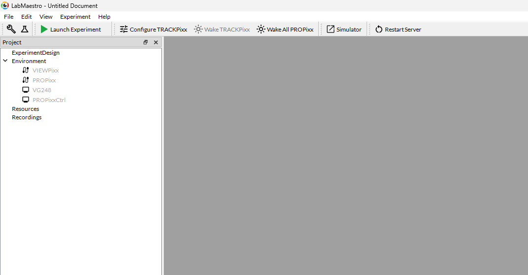
Set up Vpixx either through the LabMaestro platform (preferred) or through bash script VPutil GUI
- Or use VPutil
Open ‘VPutil’
Run ppx a and Enter,
- Check if the screen inside the MSR is on, if the screen is off then:
run ppx s, then run reset, then wait for a minute, run ppx a
- Ensure the orientation (vertical flip) of the screen inside the MSR is correct, if not:
Open LabMaestro,
On the left of the platform, choose PROPixx from the menu
Check Rear Projection box
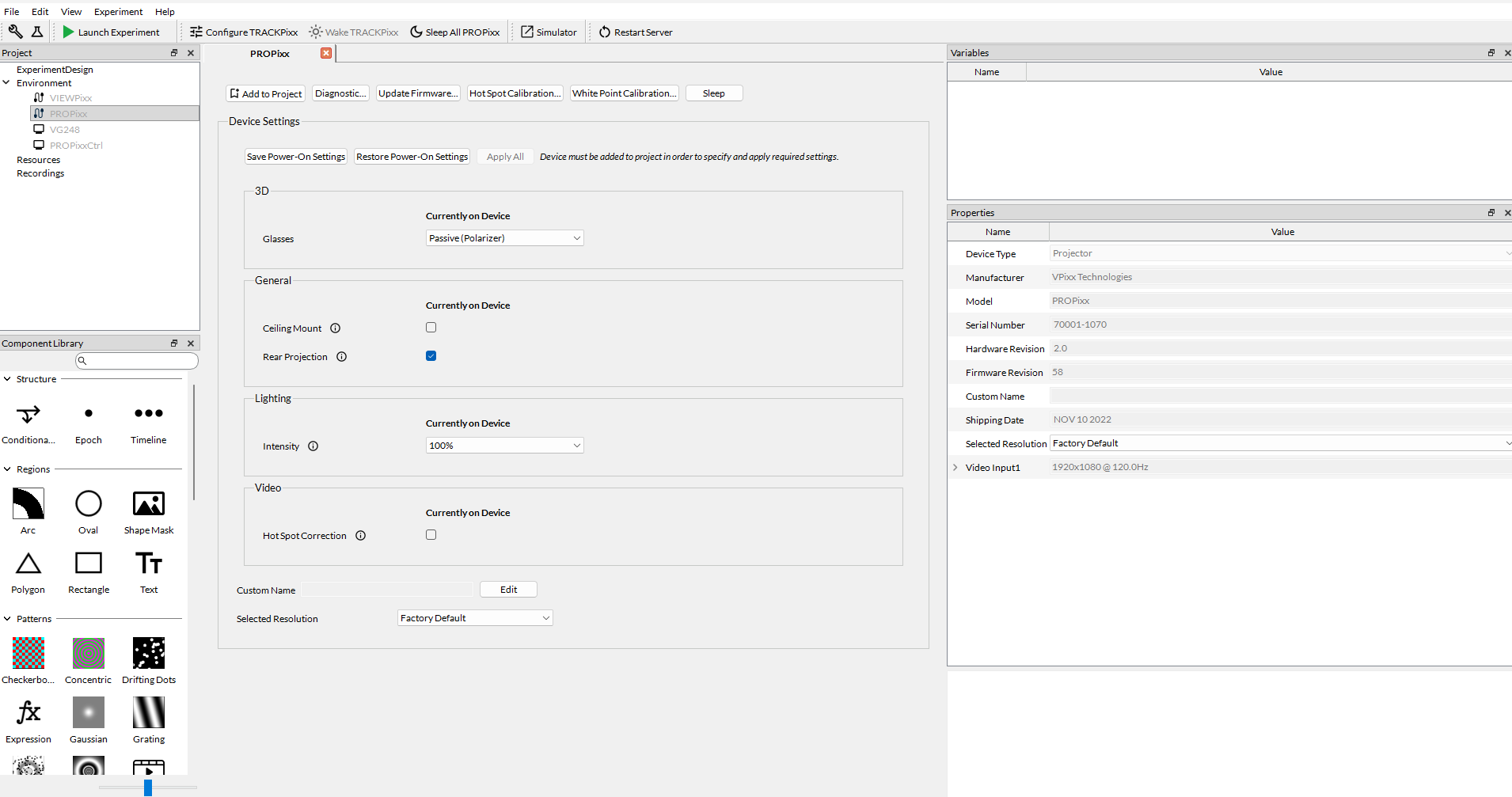
Incorrect screen orientation fix
- Verify your experiment script:
- If using PsychToolBox:
Open MATLAB (2022b)
Access your experiment .m script and launch it
Make sure you arrive to the Introduction Page mentioned in the Experiment design section. This is to ensure MEG data recording can be started before the experiment begins
You can do a quick test run to make sure that trigger signals are appearing correctly on the MEG160 software
Warning
For a real participant, make sure to turn off the Wifi on the Stimulus Computer so that the experiment is not interrupted by an update or other notification from the internet.
- Microphone inside MSR:
Make sure the sound box is switched on - located under the Stimulus computer - if not click on the green round button
- Check if you can hear the participant through the speakers, talking from inside the MSR to the microphone attached to the dewar
Participant microphone
- Earplugs
- Check the earplugs and make sure the participant can hear you
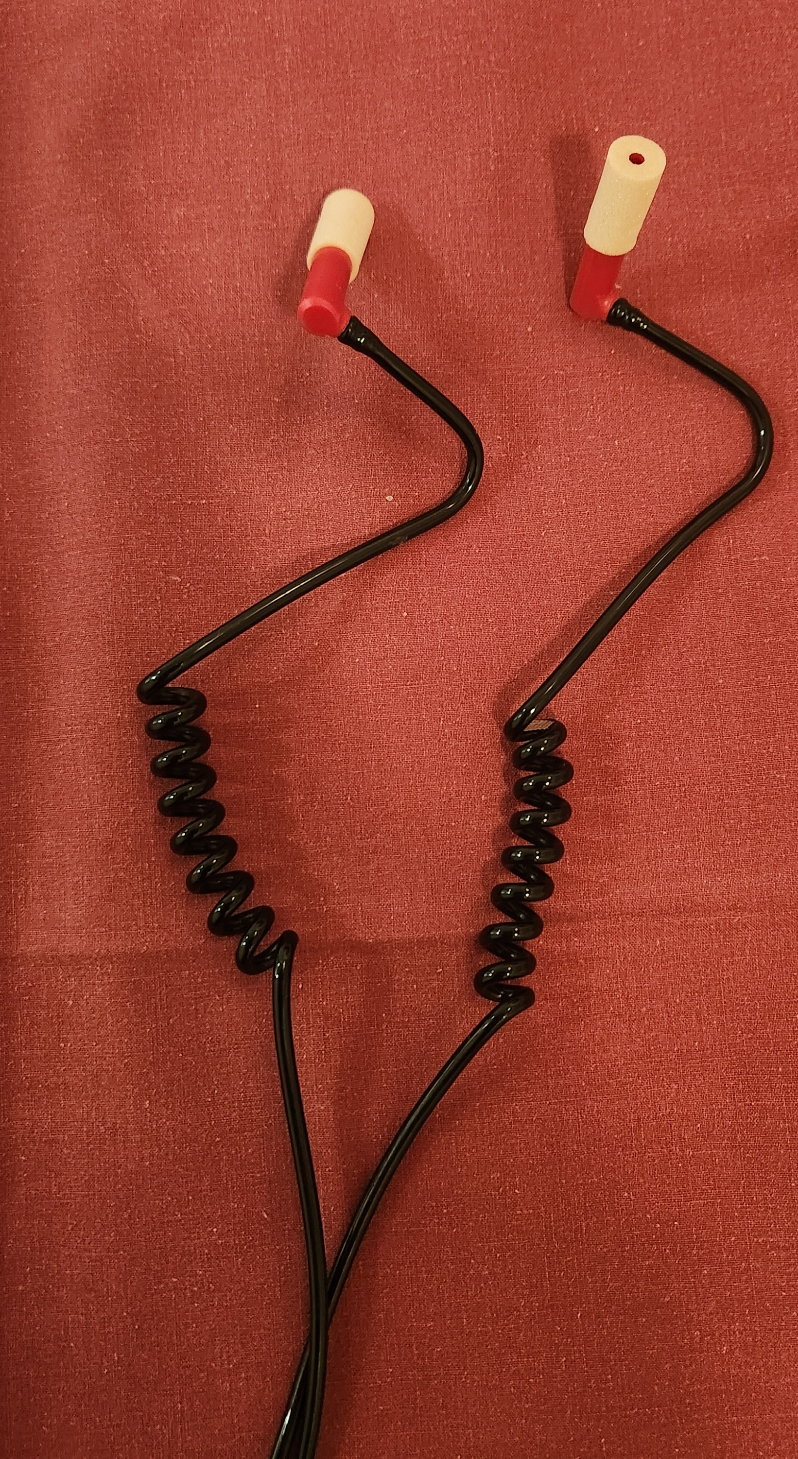
Earphones with foam earplugs
- Prepare the FastScan computer:
- If the FastScan computer is not turned on:
make sure that FastScan device is off (the flat black box next to the monitor, picture below)
turn on the computer then launch FastScanII program
turn on the FastScan device
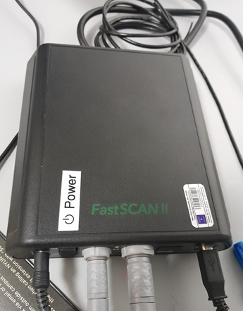
Fast Scan device
Turn-off the doorbell ring at the entrance of the lab by turning off the plug [IMAGE]
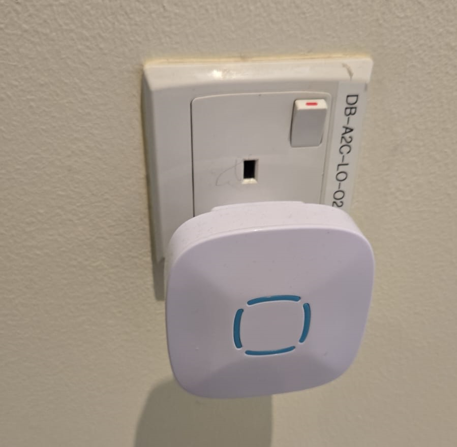
Deactivate the doorbell by pressing the plug button.
Perform the MEG Experiment (Participant is present)
- If the participant is a veil-wearing female:
place sign on door
block door with the isolation screen found behind the laser scan room door
- Welcoming the participant and providing them with explanations
[WELCOME] Thank you for joining our study. Is this your first time in the MEG?
[GENERAL OVERVIEW] No worry, Let me explain to you now what we are going to do today.
[BEFORE MEG - HEAD SHAPE] Before you are going into the MEG, we need to do some preparation.
- Explain the FastScan head laser scan:
I will scan your head shape with a laser gun [show the FastScan]
This is giving us a 3D reconstruction of the shape of your head
To do that, you need to sit there and not move for around 5-7 minutes
Moreover, I have to mark five points on your forehead and close to your ears with this [show it] washable ink,
it will disappear after just one shower [show the phantom head with the points]
Why are we doing that? To know where your head is located while you are in the MEG.
This is important for the study we are running because we need to know where the data recorded by the MEG sensors
that measure the tiny changes in the magnetic field generated by the brain activity, is coming from.
You know, different people have different head shape/size,…
and they place the head in slightly different sites relative to the MEG sensors.
Why the points? When we are in the MEG room
I will tape you small things called ‘head position coils’ in the places you have these painted points
and this will tell us where your head is relative to the MEG sensors
It looks a bit weird at the beginning, but you get used to it soon(I did the experiment on myself)
- [BEFORE MEG - CLOTHES]
Another important thing is that you cannot go inside of the MEG room with any kind of metallic object
because it will create an artifact on the MEG sensors.
To ensure that, I have to ask you to wear this MEG compatible clothes (like the ones in the hospitals).
Please, if you feel comfortable with that, you should take off your bra (most of the time there are small metallic trips or parts).
- [INSIDE MEG]
Explain the study-specific instructions here or give them an instruction manual to read.
Now, let me recap what we will do today. You need to fill the forms, scan your brain shape,
then you need to change clothes. You go to the MEG room, we tape coils in your forehead. And then, you will do the tasks.
[END OF EXPLANATION] Is everything clear? Do you have any questions? Do you feel comfortable? Are you ok? Please let me know, this is important for us that you understand everything.
- Fill up forms
Ensure that we have the electronically signed all consents and any forms needed specifically for your experiment, or allow them to fill in/sign by hand at the time of the session
- Check up MEG incompatibilities
Participants MUST change from their street clothes into scrubs provided clothing. Underwear without any metal and socks can be kept on. Bras should be removed.
Make sure they have NO metallic objects in the body/eyes
- Confirm that they do not have:
Surgical clips, artificial heart valve, implanted drug pump
Bullet
Cochlear implant or hearing aid
Dental Retainers or braces
Make-up, especially red color makeup
Hair pins
Jewelry and piercings
Keys
Phone
If the subject arrives with make-up, ask them to completely remove it
- If the subject wears glasses, ask them to remove the glasses and provide them with an MR compatible glasses from the briefcase found in the lab
- Determine their vision prescription and provide them with the closest matching pair of glasses from the briefcase.
available lens strengths for vision correction -6 to +6 in 0.5 increments
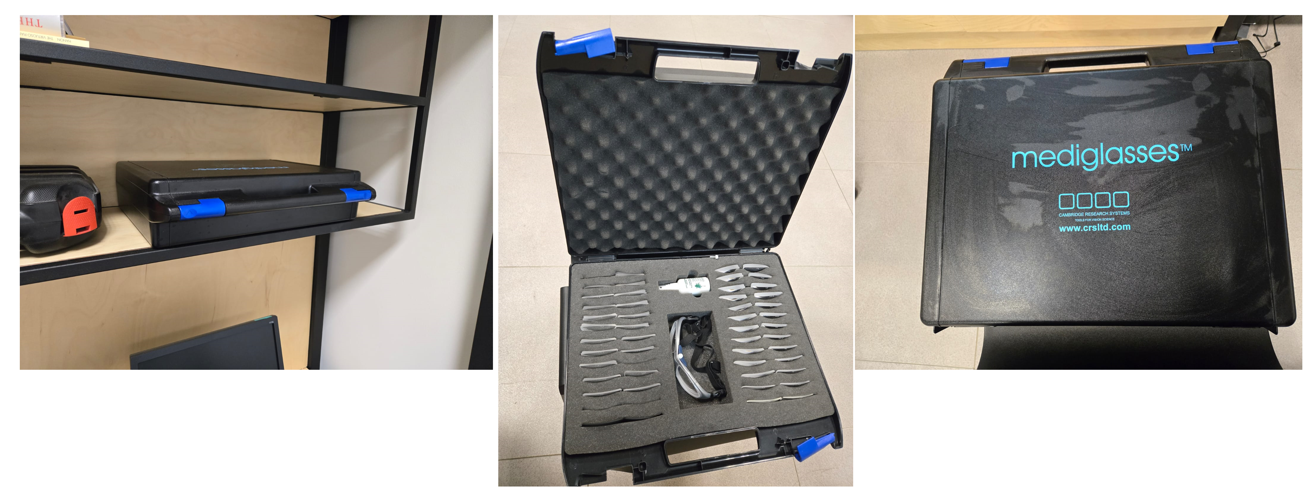
MR safe glasses briefcase.
Ask the participant to put their phone on Airplane mode
Put your own phone and all other phones in the MEG lab on airplane mode
Call the security guard on 85849 and ask them to turn off their walkie-talkies for the duration of the experiment
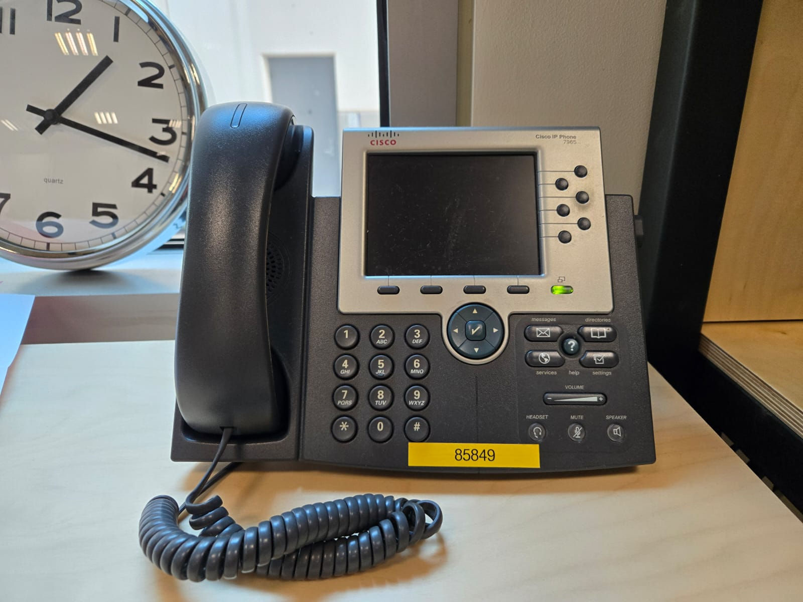
Phone in MEG lab with a label of security guard office.
- Perform the FastScan laser head scan
- Capping the participant
Put a swimming cap on the head of the participant
Make sure the cap is as smooth as possible on the participant’s head
Participants with long hair, can keep most part of their hair outside the cap behind their ears and onto the back
The ears must be clear of hair
The cap must cover all the hair that can be seen at the anterior, left and right parts of the head
Smoothen the hair under the cap as much as possible, excess long hair can be drawn to outside the cap at the cerebellum level
The goal is that the cap takes the shape of the skull at best
- Mark the fiducials - there are a total of 8
Use the “T” template, with the line aligning the participant’s nasion as in the below picture
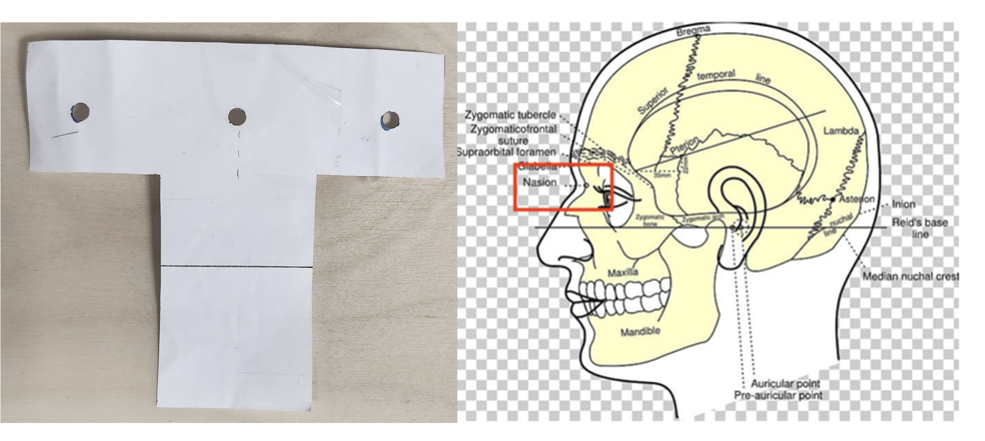
“T” template on the left and nasion/pre(auricular) positions on the right
Mark the nasion using a pen (fiducial 1)
Adjust the fold in the “T” template to the participants nasion
Using a pen marker, mark fiducials 6, 7 and 8 by using the three holes in the “T” template
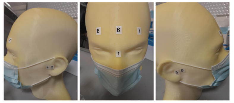
Fiducials numbered by the order they should be laser scanned with.
Mark the the right and left tragi and left and right pre-auricular regions (1cm anterior to the tragi) - (points 2, 3, 4,and 5)
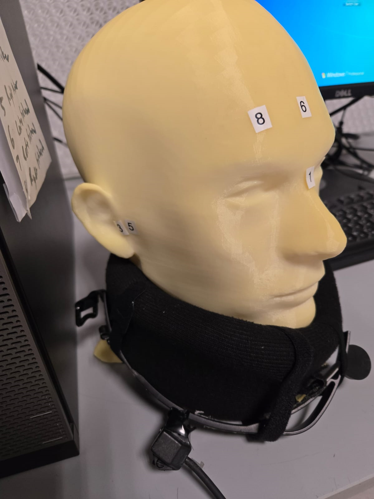
Place a tissue on the neck brace over the area closest to the mouth for sanitary purposes - see picture
Put on the neck brace
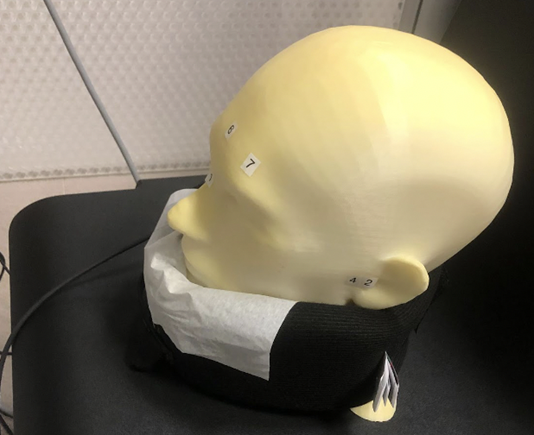
Neck brace with tissue for sanitary purposes
- Perform laser scan
- Once FastScan is finished initializing (indicated at the bottom of the software UI):
Open FastScan II software on the computer
Press ‘New’
Ensure the scanner is in Sweep mode (add [IMAGE])
Ask the participant to close their eyes and avoid any movements until scan is finished
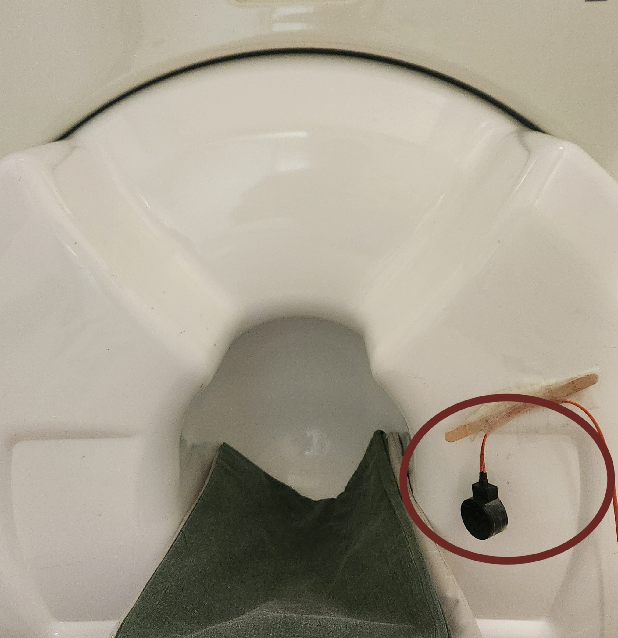
Point the laser gun at the laser scanner reference receiver (the box on the ring you place around the neck, see below) with a half-click, followed by a full click.
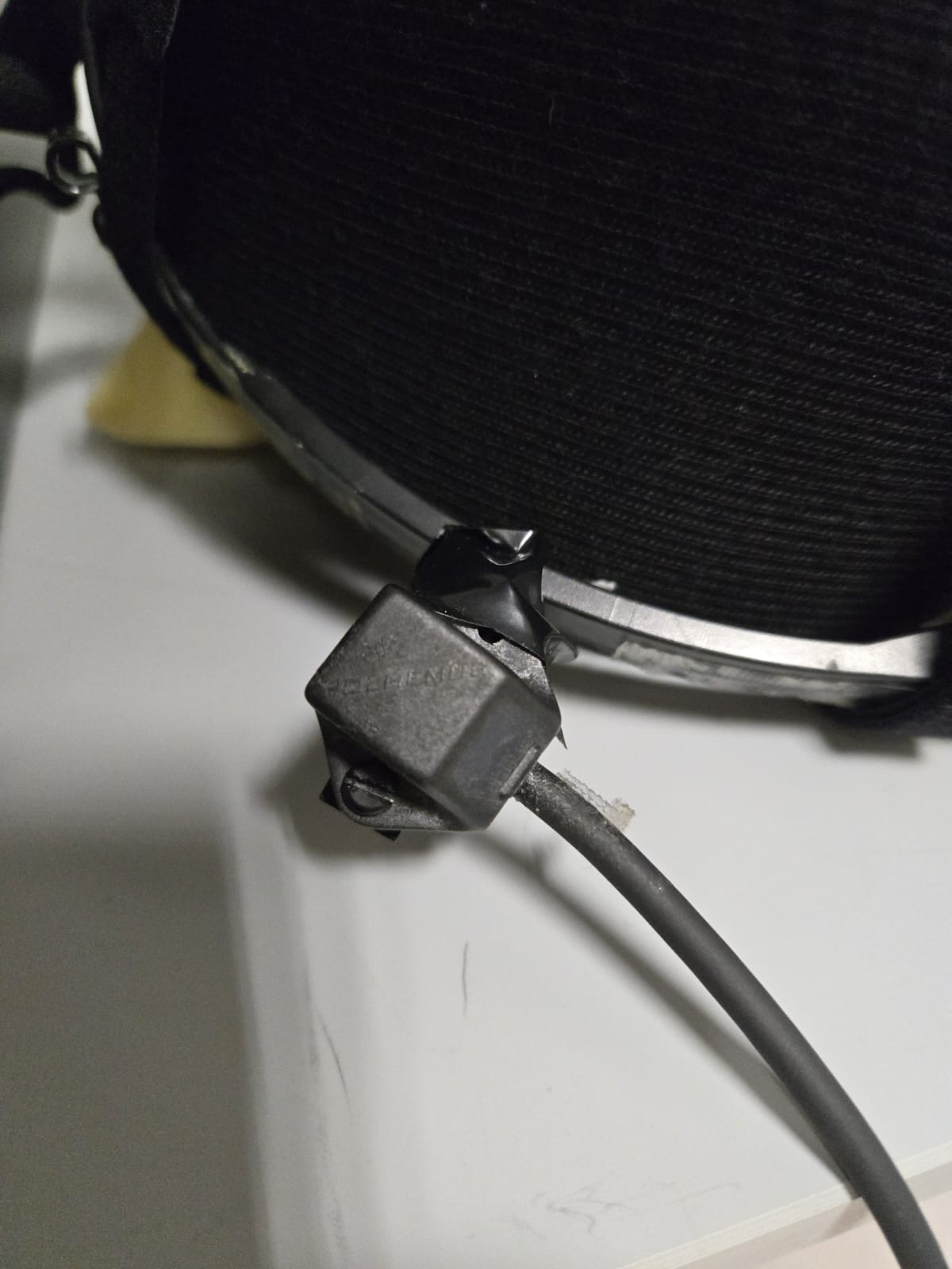
Laser scanner reference receiver
Neck brace with laser scanner reference point on the bottom left
Warning
** Error message during scanning ** If the following error message appear, this means that the laser scan device lost the reference point.
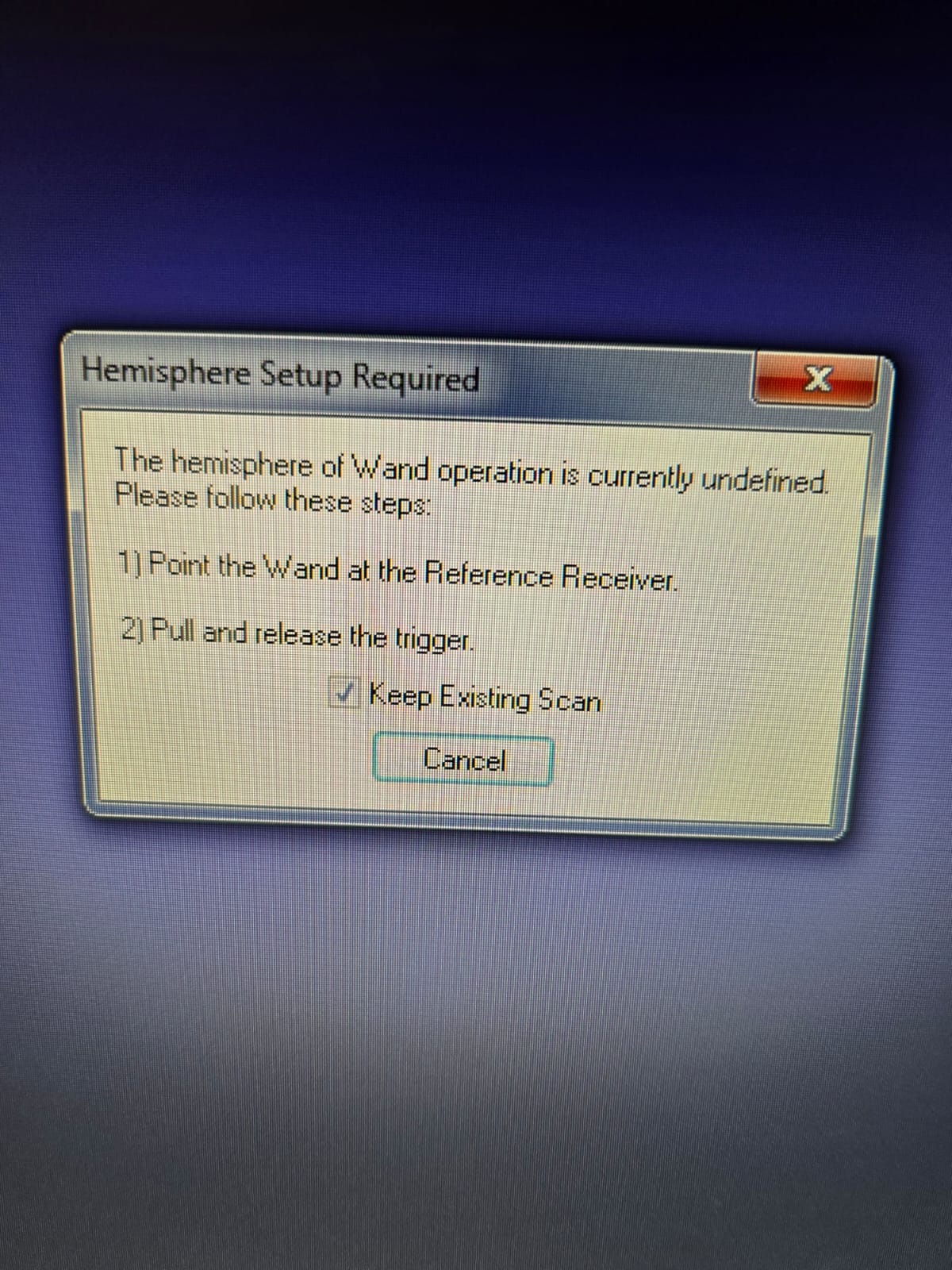
LaserScan error when device is de-referenced
Do not press Cancel on the message - point the laser scanner to the reference receiver, first with a half click to point and then a full click.
- Scan head shape (sweeps) with full click. Tips:
Include ALL cap surfaces + surfaces with fiducial points
Avoid overlapping sweeps
Making sweeps for head and face separately
Keep a consistent distance between the head and scanner throughout the scan
Hint
Press half a click while using the laser scanner to shift the view on the FastScan II software to the current view as seen from the device. This feature allows you to quickly identify areas that are not covered well by the current laser scan.
- After sweeps, switch to Laser Points and click on Stylus List for points options, ensure that Stylus > Properties > Capture Points (NOT capture lines)
- Start registering the fiducial points following this order - see picture.
- -The 8 points are as follows:
Nasion - between eye-brows at the nasal bridge
Left tragus - cartilage of left ear (not marked)
Right tragus - cartilage of right ear (not marked)
Left marker - pre-auricular marking left ear
Right marker - pre-auricular marking right ear
Center forehead - center forehead marking
Left forehead - left forehead marking
Right forehead - right forehead marking
Ensure that you have only 8 points selected on the Stylus List
Tell participant they can move back again
- Return the scanner and box to the foam holder on the table, and make sure none of the cords are on the floor
THIS IS A VERY EXPENSIVE DEVICE - see picture

FastScan should ALWAYS be placed like this: laser on foam, cables on table (not floor).
Remove the cap from the participant’s head and toss into the washing bin
Remove the neck brace
Files must be saved amd stored according to BIDS protocol format
Please refer to Data Naming and Storing: MEG
- Participant goes into the MSR
Participant should remove shoes
Subject sits on the bed facing the researcher
- Place the five Head Position Indicator (HPI) coils on the marker points
Each HPI coil is marked by a color that corresponds to the position of placement of the coil on the head
Bring the forehead markers over the top of the head so the wires are not in the participant’s face
The position of the HPI coil on the participant’s head should follow the following mapping:
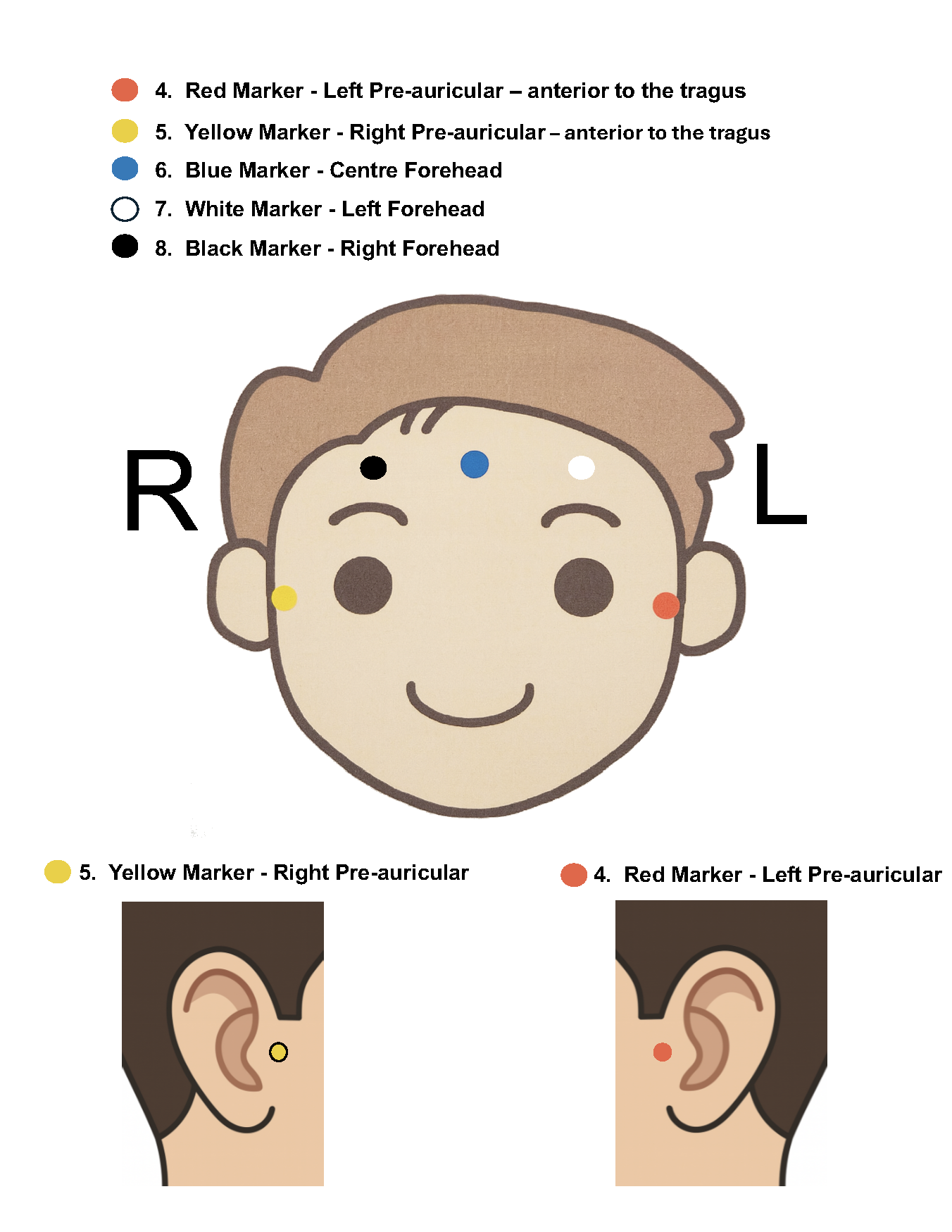
Position of Marker Coils also called Head Position Indicator (HPI) coils
As a note, the red and yellow markers should be placed in anterior to the tragus at marked points 4 and 5
Place earphones
Assist the participant with the wires while they move into the helmet
Place the pink pillow under the participant’s legs for the back support
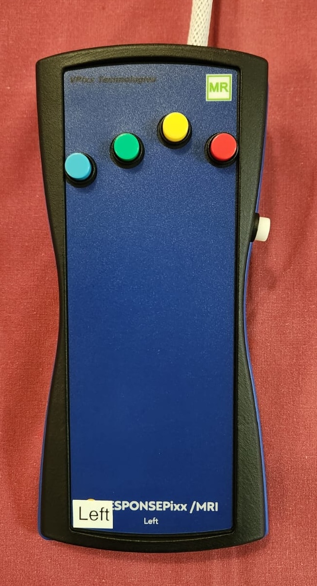
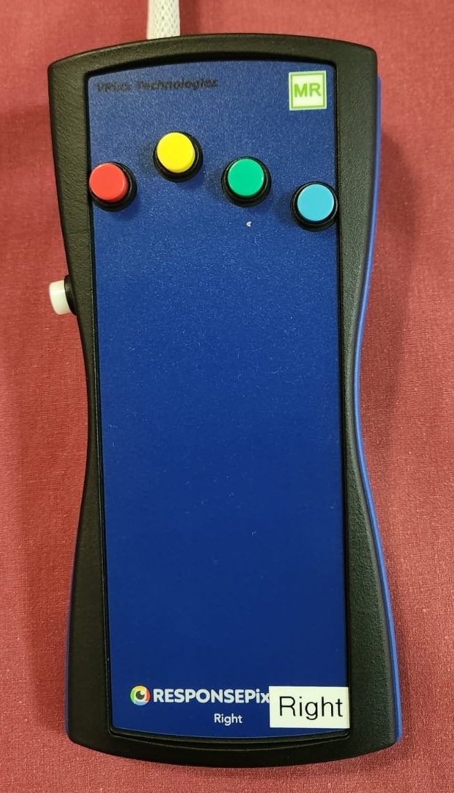
- If the experiment requires it, place the Vpixx Response Box or the Dial in their right/or left hand depending on experimental design
Optionally tape the box to the mattress, to avoid the box falling
Tape any loose wires for the markers and the button boxes
Ensure that the participant is comfortable
Close and lock the MSR door
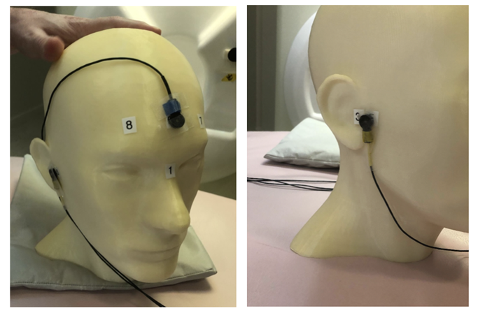
HPI Coils placement on head.
- Communicate with the participant
Turn on the microphone
Talk to the participant through the Vpixx microphone
Make sure the participant is replying back and that the voice quality is good
Tell them that the experiment is about to start and that they should refrain from any movement
Tell them that if they need to speak to you for any urgent issue, they can do this freely at any time
Turn off the microphone
- Run experiment and recording
Run your script until it lands on the Introduction Page of your script as explained in the Experiment design section.
Prepare MEG recording
- Prepare MEG recording
On ‘MEG MAIN PC’ computer, open MEG Lab (on desktop), aka MEG160
The participant is now in the MSR, door is CLOSED, the lights have been switched off and the Brightness dial has been turned to the minimum
- If empty room data has not been acquired prior to the current experiment, Auto Tuning should be performed
-Menu -> Acquire -> Auto Tuning -> Ok - Wait for the auto-tuning to be done
This should be followed by a Sensor Check
- From Menu -> Acquire -> MEG Measurement -> Monitor and Acquisition window should open
- In the ‘Sensor Control’ window ensure or set these parameters
HPF to 0.1 Hz
LPF to 500 Hz
BEF to THRU
Click on ‘Sensor Check’
Let the Sensor Check run for around 30 seconds
Uncheck ‘Sensor Check’
Make sure that the sensor display identical sinusoidal wave
Remember that Sensor 91 is broken and will not display a sine wave
- File storage location and naming convention
From the menu “Acquire (Q)”, select “MEG Measurement (Q)”
- On “Monitor and Acquisition” window > ‘Data Acquisition’
Patient ID: sub-<subjectID> [e.g., sub-001]
Patient Name: sub-<subjectID>_ses-<session-number>_task-<projectname> [e.g., sub-001_ses-01_task-resting-state]
Foldername: D:\MEGDATA\<Lab_name>\STUDY_CODE\sub-<subjectID>
“Lock” [only if MSR door is CLOSED]
Wait until MEG sensors are stable i.e. no upward or downward trend
- Perform marker measurement
Switch off microphone
On “Monitor and Acquisition” window:
Marker measurement > Start > OK - see picture
When done, column ‘GOF%’ should be around 99%
If not, at least one of the head coils is misplaced
If at least 3 head marker coils are in place - PROCEED
Click OK
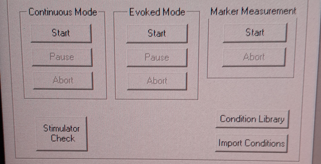
Continuous mode (left) and Marker measurement (right).
A .mrk file named as YYYYMMDD-x.mrk is automatically generated in the specified directory following the marker measurement, where x is an integer 1,2,3,… indicating the order of recording of the marker
If your experiment is lengthy i.e. 2 hours long, we recommend that you perform a marker measurement in between, i.e., after 1 hour is elapsed
- On “Monitor and Acquisition” window:
- Set/Ensure that:
HPF: 0.1 Hz
LPF: 500Hz
BEF: THRU
Continuous Mode > Start - see above picture
Sampling rate: 1000 (default)
Time: 4000 [66 minutes] (this is the maximum possible time in the MEG160 software)
Start Acquisition
At this point, you can safely start your experiment from the Stimulus computer
If your experiment is lengthy, we recommend that you perform a marker measurement in between runs
A marker measurement must be performed at the end of an experiment
- Stop continuous recording (when task finishes, or if the experiment spans for more than 4000 seconds and needs a new recording)
- On “Monitor and Acquisition” window - see picture 14:
Continuous Mode > Abort
- Finish up the MEG session (when all tasks are done!)
- On “Monitor and Acquisition” window:
‘Unlock’ [VERY IMPORTANT STEP, DO NOT OPEN THE DOOR BEFORE IT]
Close MEG160 software
- Take out participant from MSR
[ONLY WHEN SENSORS ARE UNLOCK!] Open the MSR door
When removing the head-position indicator coils and earphones, do the removal yourself. The coils in particular are very fragile and expensive. Remove with care.
Ask participant to change clothes back and put the scrubs in the wash bin (in the laser scan room)
After the MEG session
Settings MEG - Do not shut down any of the computers. They can all be locked or logged off. - Turn on the heater cable [THIS IS VERY IMPORTANT] - see picture above - Turn off the MSR lights. - Double-check that you turned the heater back on.
Clean room - Remove linen and place in bin - Clean the helmet, head-position indicator coils, and button box with wipes. - Wipe down the FastScan neck brace and any other surfaces the participant came in contact with
- Postprocessing
- Apply Noise Reduction filter using the reference magnetometers
The KIT system is equipped with reference magnetometers on channels 208 till 223, that measures the external magnetic field
- [Optional] you can noise reduce your SQUID data (channel 0-207) by applying a filter that uses the data from channels 208 to 223
Open the produced .con file in the default app MEG160 then apply a Noise Reduction filter using Edit -> Noise Reduction
Make sure the Magnetometers on channels 208, 209, 210 are used.
Execute the noise reduction, then File -> Save As -> add _NR at the end of the file name.
Transfer both files to NYU BOX as detailed in the data uploading section.
- FastScan Instructions
Open FastScanII software (icon on desktop)
Please refer to MEG-Laserscan files
To delete points you’ve selected, simply click on the backspace key on your keyboard
- Then go to Edit > Generate Surface
Smoothing = 5mm
Decimation = 3mm
In the pop-up, click on Apply Basic Surface, then close it
To save your head scan, please refer to MEG-Laserscan files
- Edit > Generate surface > Apply basic surface
Basic surface has fewer than 10,000 points
If not, decimate: Generate > Surface Simplification = 0.10 > Apply (Basic Surface)
- File > Export > save as
Please refer to MEG-Laserscan files
- Uploading to NYU BOX
You should have your own folder on NYU BOX named after your project
Refer to the Data Uploading section to upload your data
Appendix. A: Stylus location and markers


The following table is a summary of the position of each registered stylus location and whether or not a KIT coil will be placed on that position.
Index |
Body Part |
Marker Coil Information |
|---|---|---|
1 |
Nasion |
KIT: NO, OPM: |
2 |
Left Tragus |
KIT: NO, OPM: |
3 |
Right Tragus |
KIT: NO, OPM: |
4 |
Left Pre-Auricular |
KIT: YES, OPM: |
5 |
Right Pre-Auricular |
KIT: YES, OPM: |
6 |
Center Forehead |
KIT: YES, OPM: |
7 |
Left Forehead |
KIT: YES, OPM: |
8 |
Right Forehead |
KIT: YES, OPM: |
Appendix. B: Marker coils for KIT order of appearence in .mrk
The registered .mrk file containing the position of the HPI coils for KIT. Using fieldtrip function named ft_read_headshape(‘PATH TO .mrk’), we report the order of appearence of the HPI coils positions in the .mrk file below. This has been tested with many .mrk files in the current pluggin setting (last column)
Order of appearance in the .mrk |
Placing position of HPI Coil on head |
Color |
Plugging order in Marker Box |
|---|---|---|---|
1 |
Central Forehead (CF) |
Blue |
2 |
2 |
Left Pre-Auricular (LE) |
Red |
0 |
3 |
Right Pre-Auricular (RE) |
Yellow |
1 |
4 |
Left Forehead (LF) |
White |
3 |
5 |
Right Forehead (RF) |
Black |
4 |