System specification
MEG-KIT system description
MEG systems are equipped with highly sensitive sensors called SQUIDs. In order for SQUIDS to operate and become sensitive to changes of very small magnetic fields, they need to be brought to a super-conducting state (which suppresses the resistence of the material of the sensor). To reach the superconducting state, the sensors need to be cooled down to -277 degres Celsius, to achieve this temperature liquid Helium is needed. The sensors are bathed in the liquid Helium constantly. A heater system ensures that the liquid Helium stays in liquid state. The MEG-KIT system has:
208 axial gradiometers used to measure brain activity
8 orthogonally-oriented (reference) magnetometers located in the dewar but away from the brain area, used to measure and reduce external noise offline
32 open positions, of which we currently use 8 to record stimulus triggers
24 channels to record Eye Tracker data directly, auditory signals from our mixer and vocalization information from our optoacoustic fiber-optic microphone
NYUAD MEG system uses liquid helium to keep our SQUID sensors cold (-269°C, -452°F). If the helium tank leaks, the liquid helium will immediately boil off. This can cause rapid suffocation and severe frostbite. Handle with care. Especially don’t shock the dewar. If you feel anything strange while doing an experiment (i.e., you suspect a helium leak), open the MSR and release the subject immediately. Do not leave the room with a subject in the MSR.
Important
Since 2018, the gradiometer sensor mapped to channel 091 in KIT indexing is irreparably damaged. Since the incident, the sensor has been statically typed as a magnetometer, this ensures that the data from this sensor is not processed automatically during analysis in the provided pipelines. The channel displays a TTL squared signal during a data acquisition.
LAB setup
Lab setup: Outside the MSR
Computers
MEG DAQ PC: used to acquire the MEG data, has four screens for visualising sensor data in real time
- stimulus1 pc: used to run the experiments, has two screens for visualising code on the bottom screen and experiment on the top screen acting as a mirror to the projected image inside the MSR
Vpixx stimulus/projector system
Propixx (Screen projector)
The Vpixx Propixx system projects visual stimuli on a screen of width of 65 cm
Lab setup: Inside the MSR
The MSR is equipped with dimmable 6 halogen light bulbs. Replacement ones are found in the lab incase of needing to change. Backup battery is located in one of the office spaces connected via yellow cables
Lights: switch is located by the door
Dewar: contains liquid helium that submerges SQUID sensors spread across the helmet
Foam insert headphones: allows participants to get audio stimulus but also audio indications from the operator
Marker box: connects the head position indicator coils (marked with 5 colours)
Heater cable: keeps frost and ice from forming on DEWAR; switch is located at the back of the MSR
Projector: back-projects stimulus onto a screen; remote control is outside the room.
Amplitude switches: controls the signal strength of the marker coils


Electronic lag times between visual stimulus and KIT trigger box
A trigger signal, representing a visual stimulus sent from the Vpixx system to the KIT DAQ computers arrives slightly prior to the visual stimulus from the Vpixx projector due to the electronic circuits. This result has been deeply investigated by Gayathri Satheesh after performing a photodiode experiment with 1000 trial. Gayathri used 1000 trials with a 1000 Hz sampling frequency her findings summarises as:
the mean lag from the is -8.27852 ms (the negative means the trigger signal appears on the data 8.27 ms before the subject has seen the visual stimulus)
the standard deviation of the lag is 0.534153 ms
the maximum value was 11ms
the minimum value was 8ms
Therefore, when processing the MEG data that requires 1 millisecond precision, the user can correct the visual stimulus trigger signals by adding an 8.2 ms shift in the increasing order of time.
MEG-Channels
Note
The numbering of channels on the KIT data acquisition software called MEG 160 starts with index 0, however in MATLAB processing, channels start with index 1.
MEG-KIT sensor channels
Channels 0 to 90 and 92 to 207: Gradiometers SQUIDS
Channel 91: broken gradiometer sensor typed as Reference magnetometer to avoid
Channels 208-223: Magnetometers for reference magnetic field (these are used to denoising and to understand the ambiant magnetic field the environment)
Vpixx Stimulus channels
These channels are free to be used by the experiment designer, they can be used as a binary signal of 8 bits
224: Event marker bit 0
225: Event marker bit 1
226: Event marker bit 2
227: Event marker bit 3
228: Event marker bit 4
229: Event marker bit 5
230: Event marker bit 6
231: Event marker bit 7
MEG-Racks
The KIT-MEG system has 7 racks
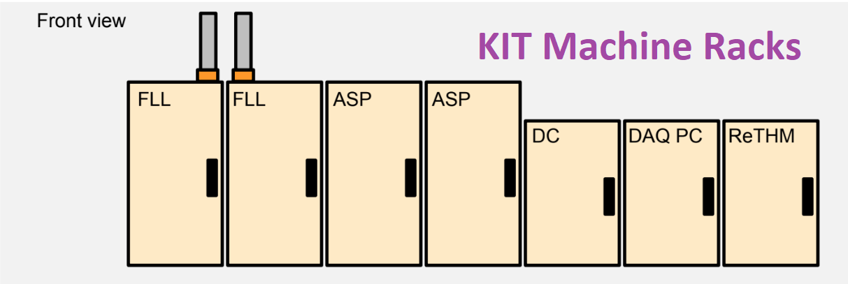
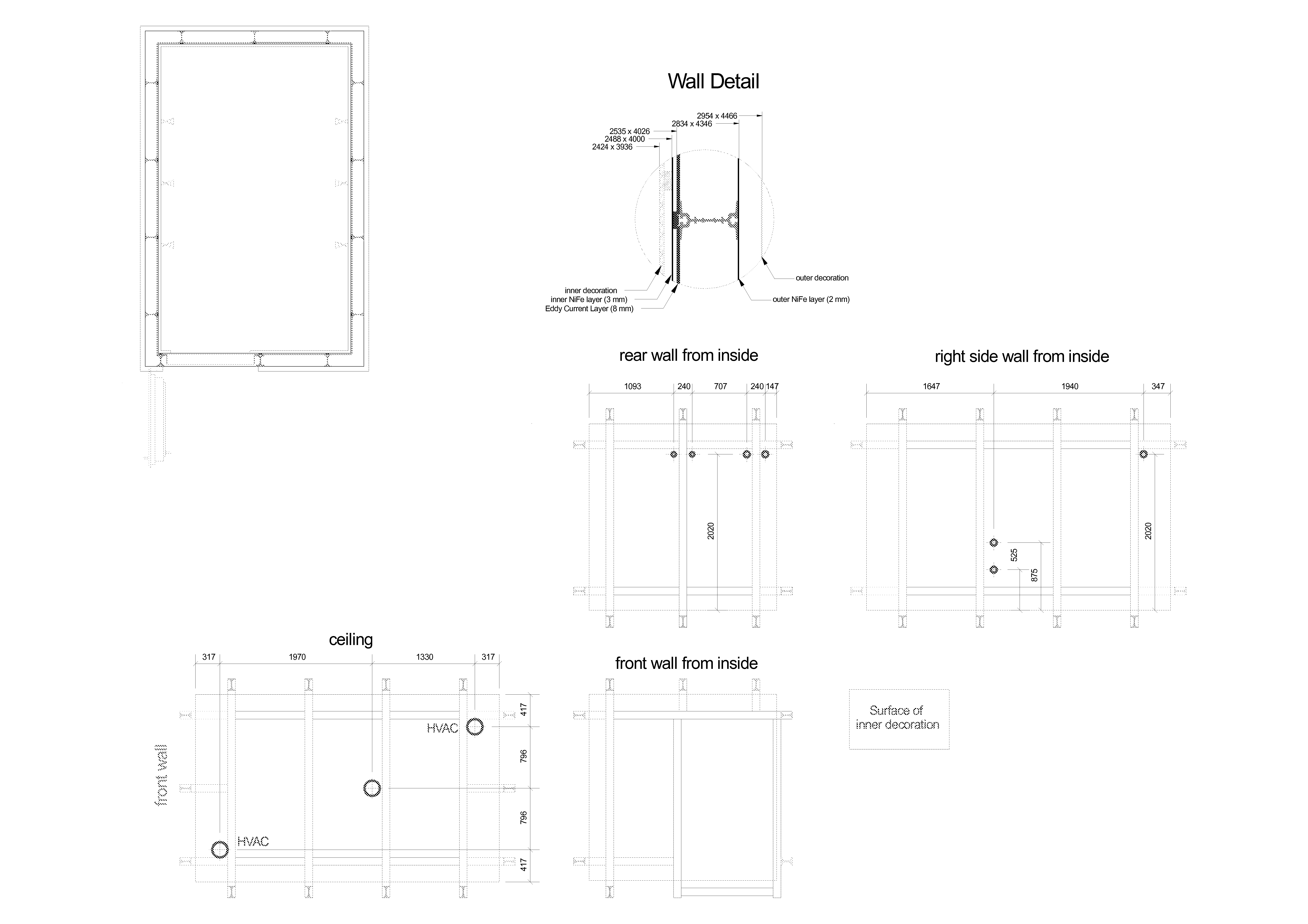
MSR: Magnetically Shielded Room
The KIT-MEG is located in an MSR built by VacuumShmelze


Consists of four PCs working together, interfacing with MEG160 during data acquisition.
- The DAQ units are located in a cabinet labeled “DAQ”.
The units are labelled as ‘DAQ0’, ‘DAQ1’, ‘DAQ2’, and ‘DAQ3’.
The last time the system battery for DAQ0 was changed on February 4, 2020.
- Once changed, the BIOS settings might need to be updated. To enter the setting page, strike F2 while the system is booting.
Make sure Power Management is Enabled.
Make sure Low Power Mode is Disabled.
In case one/some of the DAQs won’t boot, try turning it on by manually pressing the power button on the unit.
Inform other lab members if things like that happen. Chances are, they have encountered similar/same problems.
MEG160 Software parameters
MEG160 is the main software for data acquisition from the KIT-MEG system.
Auto-tuning should be performed prior to any data acquisition. From the software –> Acquire Measurement Sensor check can be performed from this window, this ensures that the sensors circuits are correct when a sinusoidal wave is seen on the channel corresponding to that sensor.
The following table shows the default parameters that should be set in the acquiring window
Parameter |
Description |
Value |
Value description |
|---|---|---|---|
HPF |
High Pass Filter |
0.1Hz |
Let pass only above 0.1 Hz (because electronic circuits generate a small noise below 0.1Hz) |
LPF |
Low Pass Filter |
500Hz |
Let pass only below 500 Hz |
BEF |
Bandwith Filter |
THRU |
Let pass all frequencies (BEF turned off) |
If we see a strong noise on a specific frequency (for example 50Hz) and would like to filter that, we use the BEF on 50Hz.
Frequently asked questions (FAQ)
Can locking the SQUID sensors and opening the MSR door damage the SQUIDs?
Opening the magnetically shielded room (MSR) door while the SQUID sensors are locked may cause the output of some channels to appear flat. However, this does not indicate permanent damage to the sensors. The temporary signal suppression is typically due to large magnetic field fluctuations from external magnetic field penetrating to the inside of the MSR. The sensors are not malfunctioning; rather, they momentarily lose proper operating conditions because of the external magnetic disturbance. Once the MSR door is closed, unlocking and then relocking the SQUIDs, autotuning restores normal sensor function.
How to test trigger channels while opening the MSR?
In such scenario, do not lock the sensors, keep the MSR door open and perform all tests with Vpixx response boxes, microphone and other hardware to test your experiment
Contact
Name |
Number |
Role |
|
|---|---|---|---|
Hadi Zaatiti |
+971 56 275 4921 |
Research Scientist |
|
Osama Abdullah |
NA |
Senior Scientist |
|
Yoshiaki Adachi |
NA |
MEG-KIT machine constructor reference |
|
Jun Kawai |
NA |
MEG-KIT machine constructor reference |
References
The following is a list of references for further understanding on MEG systems
- MNE-Python: Overview and tutorials
- Marijn van Vliet’s “Introduction to MNE-Python”
- Processing and analysis scripts from various Nellab members/alumni
- Kit2fiff and ICA examples:
- Books:
Hansen, Peter & Kringelbach, Morten & Salmelin, Riitta. (2010). MEG: An introduction to methods. 10.1093/acprof:oso/9780195307238.001.0001.
Knösche, Thomas & Haueisen, Jens. (2022). EEG/MEG Source Reconstruction, Textbook for Electro-and Magnetoencephalography. 10.1007/978-3-030-74918-7.
Hari, MD, PhD, Riitta, and Aina Puce, PhD, MEG-EEG Primer, 1 (New York, 2017; online edn, Oxford Academic, 1 Mar. 2017), accessed 18 July 2024.
Tobimatsu, Shozo, and Ryusuke Kakigi, eds. Clinical applications of magnetoencephalography. No. 8564. Springer Japan, 2016.